
In numerous scenarios such as industrial gas supply, food preservation, welding protection, and dry ice manufacturing, the stable output of gaseous carbon dioxide that meets pressure and temperature requirements is a crucial link in ensuring smooth production processes. Many purchasing engineers often only focus on the nominal gasification capacity of the equipment, but overlook the operational logic details of the cryogenic liquid carbon dioxide gasifier, ultimately resulting in problems such as gas with liquid present, non-compliant temperature, and excessive energy consumption. Today, from the perspective of actual industrial applications, we will dissect how this equipment safely and efficiently converts -196℃ grade cryogenic liquid CO2 into usable gaseous medium.
Ⅰ. Special physical characteristics of cryogenic liquid CO2: The core prerequisite for gasification
Unlike ordinary ambient temperature gases, the storage state of cryogenic liquid carbon dioxide is extremely sensitive to environmental parameters. It is usually stored in a pressurized liquid form in a cryogenic storage tank. Any slight fluctuation in the ambient temperature can easily lead to local vaporization, causing overpressure risks. If liquid CO2 is directly connected to the gas supply end, it will not only cause ice blockages in the pipeline but also may cause the welding protection gas to be interrupted or the food-grade CO2 purity to fail to meet the standards due to unstable medium state. It is precisely because of these characteristics that specialized cryogenic gasification equipment has become an indispensable part in centralized gas supply systems, as it can complete the phase change process under controlled conditions and avoid various safety hazards caused by direct gasification.
Ⅱ. Two core working paths of mainstream gasifiers
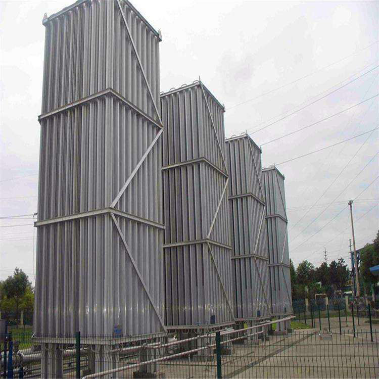
The most widely used cryogenic liquid CO2 gasifiers in industrial scenarios are mainly divided into two types: air-cooled and electric water bath types. Their phase change logic has different focuses and are suitable for different working conditions:
1.Natural heat exchange logic of air-cooled gasifiers
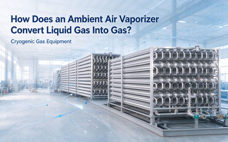
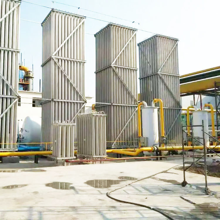
This type of equipment relies on the atmospheric environment as the heat source and uses star-shaped aluminum finned tubes as the core heat exchange components. By taking advantage of the extremely large heat-conducting area of the star-shaped tubes, the cryogenic liquid CO2 flows through the tube body and fully absorbs the heat from the air during the phase change process. This entire process does not require additional energy consumption and can stably output gaseous CO2 under normal ambient temperatures above 0℃, making it the preferred solution for most small-scale gas usage scenarios. In our on-site tests with northern customers, we found that a gasifier suitable for a 100m³/h specification in an environment of 10℃ can maintain an out-gas temperature above 0℃ for 8 consecutive hours, fully meeting the basic requirements for ordinary welding gas.
2.Heating logic of electric water bath gasifiers
In northern winters where the ambient temperature is below -10℃ or in scenarios where the out-gas temperature at the gas supply end needs to be maintained at 5℃ or above, air-cooled gasifiers often experience insufficient heat exchange. At this time, an electric water bath gasifier will be connected to the system as a secondary heating device. It uses water as the heat medium and maintains the water temperature within the set range through electric heating tubes, allowing the cryogenic CO2 flowing through the stainless steel coil to fully absorb the heat from the water, completing the gasification and raising the medium temperature. Many food-grade dry ice manufacturing production lines will adopt the combination scheme of “air-cooled initial gasification + water bath heating” to reduce long-term energy consumption and ensure the absolute stability of the gas state during peak gas usage.
Ⅲ. Three key design details for ensuring long-term stable operation
Many purchasing customers have reported that some low-priced gasifiers experience a sudden drop in heat exchange efficiency after using for half a year. The core reason is that they overlooked three key structural designs:
First, regarding the material selection of the heat exchange tubes, inferior equipment uses ordinary aluminum alloy tubes, which are prone to stress cracking when exposed to low-temperature media over a long period. However, qualified industrial-grade products use star-shaped tubes that are resistant to low temperatures. The designed temperature range covers -196℃ to 65℃, and they are suitable for various low-temperature media such as liquid oxygen, nitrogen, and argon. The service life can reach over 10 years.
Second, the matching design of the pipe outlet diameters. The inlet port adopts a DN25 specification, and the outlet port adopts a DN40 specification. This differentiated design can effectively prevent insufficient heat exchange caused by the rapid flow rate of liquid media at the inlet end. The phase change process can be completed uniformly within the heat exchange tubes.
Third, the reserved safety relief structure. Regular equipment will set relief valves at key positions of the tube group. In case of local ice blockage and overpressure, it can automatically release the pressure to avoid potential safety hazards.
Ⅳ.the key points of adapting to specific operating conditions that are often overlooked during selection.
Many users only mark the rated gasification volume during selection but do not adjust the parameters based on their actual usage scenarios. For example, in an environment with low air pressure in high-altitude areas, the actual heat exchange efficiency of the air-cooled gasifier will be about 20% lower than in plain areas. During selection, sufficient margin needs to be reserved; if it is a large-scale production line that operates 24 hours continuously, a large-sized equipment with an gasification volume of 1000m³/h or above should be selected, along with a dual-pipe switching design to avoid thick frost accumulation on a single equipment during long-term continuous operation. We have encountered a car welding factory that initially selected a single 500m³/h gasifier based on conventional conditions. During double-shift continuous production, the equipment developed a large area of frost accumulation after 4 hours of operation, and the outlet gas temperature dropped sharply to -10℃. After replacing it with two 800m³/h parallel devices, the stability of the entire gas supply system was completely resolved.
If you are selecting and adapting a low-temperature liquid CO2 gasifier for your production line, or if you encounter problems with liquid discharge from the equipment or non-compliant temperatures, please feel free to consult Zhuoyue Gas Equipment. We will provide you with customized solutions based on your specific situation.